缓冲区与索引
终于要讨论它们了!
你可能已经厌倦了我老说 "我们会在讨论缓冲区的时候再详细介绍" 之类的话。现在终于到了谈论缓冲区的时候了,但首先...
什么是缓冲区?
缓冲区(Buffer)一个可用于 GPU 操作的内存块。缓冲区数据是以线性布局存储的,这意味着分配的每个字节都可以通过其从缓冲区开始的偏移量来寻址,但要根据操作的不同而有对齐限制。
缓冲区常用于存储结构体或数组等简单的数据,但也可以存储更复杂的数据,如树等图结构(只要所有节点都存储在一起,且不引用缓冲区以外的任何数据)。我们会经常用到缓冲区,所以让我们从最重要的两个开始:顶点缓冲区(Vertex Buffer)和索引缓冲区(Index Buffer)。
顶点缓冲区
之前我们是直接在顶点着色器中存储的顶点数据。这在学习的起始阶段很有效,但这不是长远之计,因为需要绘制的对象的类型会有不同的大小,且每当需要更新模型时就得重新编译着色器,这会大大减慢我们的程序。我们将改为使用顶点缓冲区来存储想要绘制的顶点数据。在此之前,需要创建一个新的结构体来描述顶点:
// lib.rs
#[repr(C)]
#[derive(Copy, Clone, Debug)]
struct Vertex {
    position: [f32; 3],
    color: [f32; 3],
}每个顶点都会有一个位置(position)和颜色(color)字段。位置代表顶点在三维空间中的 x、y 和 z 坐标。颜色是顶点的红、绿、蓝三通道色值。我们需要令 Vertex 支持 Copy trait,这样就可以用它创建一个缓冲区。
接下来,需要构成三角形的实际顶点数据。在 Vertex 下面添加以下代码:
// lib.rs
const VERTICES: &[Vertex] = &[
    Vertex { position: [0.0, 0.5, 0.0], color: [1.0, 0.0, 0.0] },
    Vertex { position: [-0.5, -0.5, 0.0], color: [0.0, 1.0, 0.0] },
    Vertex { position: [0.5, -0.5, 0.0], color: [0.0, 0.0, 1.0] },
];按逆时针顺序排列顶点:上、左下、右下。这样做的部分理由是出于惯例,但主要是因为我们在 render_pipeline 的 primitive 中指定了三角形的 front_face 是 Ccw(counter-clockwise),这样就可以做背面剔除。这意味着任何面向我们的三角形的顶点都应该是按逆时针顺序排列。
现在有了顶点数据,需要将其存储在一个缓冲区中。让我们给 WgpuApp 添加再一个 vertex_buffer 字段:
// lib.rs
struct WgpuApp {
    // ...
    render_pipeline: wgpu::RenderPipeline,
    // 新添加!
    vertex_buffer: wgpu::Buffer,
    // ...
}接着在 new() 函数中创建顶点缓冲区:
// new()
let vertex_buffer = device.create_buffer_init(
    &wgpu::util::BufferInitDescriptor {
        label: Some("Vertex Buffer"),
        contents: bytemuck::cast_slice(VERTICES),
        usage: wgpu::BufferUsages::VERTEX,
    }
);为了访问 Device 上的 create_buffer_init 方法,我们须导入 DeviceExt 扩展 trait。关于扩展 trait 的更多信息,请查看这篇文章。
要导入扩展 trait,只需在 lib.rs 的顶部放上这一行:
use wgpu::util::DeviceExt;你应该注意到我们使用了 bytemuck 来将 VERTICES 转换为 &[u8]。create_buffer_init() 函数的参数类型是 &[u8],而 bytemuck::cast_slice 为我们实现了此类型转换。为此需在 Cargo.toml 中添加以下依赖项:
bytemuck = { version = "1.19", features = [ "derive" ] }我们还需要实现两个 trait 来使 bytemuck 工作。它们是 bytemuck::Pod 和 bytemuck::Zeroable。 Pod 表示 Vertex 是 "Plain Old Data" 数据类型,因此可以被解释为 &[u8] 类型。Zeroable 表示可以对其使用 core::mem::zeroed()。下面修改 Vertex 结构体来派生这些 trait:
#[repr(C)]
#[derive(Copy, Clone, Debug, bytemuck::Pod, bytemuck::Zeroable)]
struct Vertex {
    position: [f32; 3],
    color: [f32; 3],
}当结构体里包含了没有实现 Pod 和 Zeroable 的类型时,就需要手动实现这些 trait。这些 trait 不需要我们实现任何函数,只需像下面这样来让代码工作:
unsafe impl bytemuck::Pod for Vertex {}
unsafe impl bytemuck::Zeroable for Vertex {}最终,我们可以把 vertex_buffer 添加到 WgpuApp 结构体中了:
Self {
    // ...
    render_pipeline,
    vertex_buffer,
}接下来怎么做?
我们需要告诉 render_pipeline 在绘制时使用这个缓冲区,但首先需要告诉它如何读取此缓冲区。顶点缓冲区布局(VertexBufferLayout)对象和 vertex_buffers 字段可以用来完成这件事,我保证在创建 render_pipeline 时会详细讨论这个问题。
顶点缓冲区布局对象定义了缓冲区在内存中的表示方式,render_pipeline 需要它来在着色器中映射缓冲区。下面是填充了顶点的一个缓冲区的布局:
wgpu::VertexBufferLayout {
    array_stride: core::mem::size_of::<Vertex>() as wgpu::BufferAddress, // 1.
    step_mode: wgpu::VertexStepMode::Vertex, // 2.
    attributes: &[ // 3.
        wgpu::VertexAttribute {
            offset: 0, // 4.
            shader_location: 0, // 5.
            format: wgpu::VertexFormat::Float32x3, // 6.
        },
        wgpu::VertexAttribute {
            offset: core::mem::size_of::<[f32; 3]>() as wgpu::BufferAddress,
            shader_location: 1,
            format: wgpu::VertexFormat::Float32x3,
        }
    ]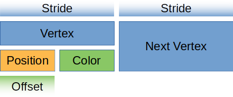
}array_stride定义了一个顶点所占的字节数。当着色器读取下一个顶点时,它将跳过array_stride的字节数。在我们的例子中,array_stride 是 24 个字节。step_mode告诉管线此缓冲区中的数组数据中的每个元素代表的是每个顶点还是每个实例的数据,如果只想在开始绘制一个新实例时改变顶点,就可以设置为VertexStepMode::Instance。在后面的教程里我们会讲解实例化绘制。attributes描述顶点的各个属性(Attribute)的布局。一般来说,这与结构体的字段是 1:1 映射的,在我们的案例中也是如此。offset定义了属性在一个顶点元素中的字节偏移量。对于第一个属性,偏移量通常为零。其后属性的偏移量应为在其之前各属性的size_of之和。shader_location告诉着色器要在什么位置存储这个属性。例如@location(0) x: vec3f在顶点着色器中对应于Vertex结构体的position字段,而@location(1) x: vec3f对应color字段。format告诉着色器该属性的数据格式。Float32x3对应于着色器代码中的vec3f。我们可以在一个属性中存储的最大值是Float32x4(Uint32x4和Sint32x4也可以)。当我们需要存储比Float32x4更大的东西时请记住这一点。
对于视觉学习者来说,我们的顶点缓冲区看起来是这样的:
让我们在 Vertex 上创建一个静态函数来返回此布局对象:
// lib.rs
impl Vertex {
    fn desc<'a>() -> wgpu::VertexBufferLayout<'a> {
        wgpu::VertexBufferLayout {
            array_stride: core::mem::size_of::<Vertex>() as wgpu::BufferAddress,
            step_mode: wgpu::VertexStepMode::Vertex,
            attributes: &[
                wgpu::VertexAttribute {
                    offset: 0,
                    shader_location: 0,
                    format: wgpu::VertexFormat::Float32x3,
                },
                wgpu::VertexAttribute {
                    offset: core::mem::size_of::<[f32; 3]>() as wgpu::BufferAddress,
                    shader_location: 1,
                    format: wgpu::VertexFormat::Float32x3,
                }
            ]
        }
    }
}像上边那样指定属性是非常冗长的。我们可以使用 wgpu 提供的 vertex_attr_array 宏来清理一下。现在 VertexBufferLayout 变成了这样:
wgpu::VertexBufferLayout {
    array_stride: core::mem::size_of::<Vertex>() as wgpu::BufferAddress,
    step_mode: wgpu::VertexStepMode::Vertex,
    attributes: &wgpu::vertex_attr_array![0 => Float32x3, 1 => Float32x3],
}这无疑很棒,但 Rust 认为 vertex_attr_array 的结果是一个临时值,所以需要进行调整才能从一个函数中返回。我们可以将VertexBufferLayout 的生命周期改为 'static,或者使其成为 const。示例如下:
impl Vertex {
    const ATTRIBS: [wgpu::VertexAttribute; 2] =
        wgpu::vertex_attr_array![0 => Float32x3, 1 => Float32x3];

    fn desc<'a>() -> wgpu::VertexBufferLayout<'a> {
        use core::mem;

        wgpu::VertexBufferLayout {
            array_stride: mem::size_of::<Self>() as wgpu::BufferAddress,
            step_mode: wgpu::VertexStepMode::Vertex,
            attributes: &Self::ATTRIBS,
        }
    }
}不管怎么说,我觉得展示数据如何被映射是件好事,所以暂时不会使用这个宏。
现在我们可以在创建 render_pipeline 时使用它了:
let render_pipeline = device.create_render_pipeline(&wgpu::RenderPipelineDescriptor {
    // ...
    vertex: wgpu::VertexState {
        // ...
        buffers: &[
            Some(Vertex::desc()),
        ],
    },
    // ...
});还需要在渲染函数中实际设置顶点缓冲区,否则程序会崩溃。
// render()
render_pass.set_pipeline(&self.render_pipeline);
// 新添加!
render_pass.set_vertex_buffer(0, self.vertex_buffer.slice(..));
render_pass.draw(0..3, 0..1);set_vertex_buffer 函数接收两个参数,第一个参数是顶点缓冲区要使用的缓冲槽索引。你可以连续设置多个顶点缓冲区。
第二个参数是要使用的缓冲区的数据片断。你可以在硬件允许的情况下在一个缓冲区中存储尽可能多的对象,所以 slice 允许我们指定使用缓冲区的哪一部分。我们用 .. 来指定整个缓冲区。
在继续之前,我们需要修改 render_pass.draw() 的调用来使用 VERTICES 所指定的顶点数量。在 WgpuApp 中添加一个num_vertices,令其值等于 VERTICES.len():
// lib.rs

struct WgpuApp {
    // ...
    num_vertices: u32,
}

impl WgpuAppAction for WgpuApp {
    async fn new(window: Arc<winit::window::Window>) -> Self {
        // 创建 wgpu 应用
        let app = AppSurface::new(window).await;
        // ...
        let num_vertices = VERTICES.len() as u32;

        Self {
            app,
            size,
            size_changed: false,
            render_pipeline,
            vertex_buffer,
            num_vertices,
        }
    }
}然后在绘制命令中使用它:
// render
render_pass.draw(0..self.num_vertices, 0..1);在上面的修改生效之前,还需要更新着色器,以便从顶点缓冲区中获取数据。
// 顶点着色器

struct VertexInput {
    @location(0) position: vec3f,
    @location(1) color: vec3f,
};

struct VertexOutput {
    @builtin(position) clip_position: vec4f,
    @location(0) color: vec3f,
};

@vertex
fn vs_main(
    model: VertexInput,
) -> VertexOutput {
    var out: VertexOutput;
    out.color = model.color;
    out.clip_position = vec4f(model.position, 1.0);
    return out;
}

// 片元着色器

@fragment
fn fs_main(in: VertexOutput) -> @location(0) vec4f {
    return vec4f(in.color, 1.0);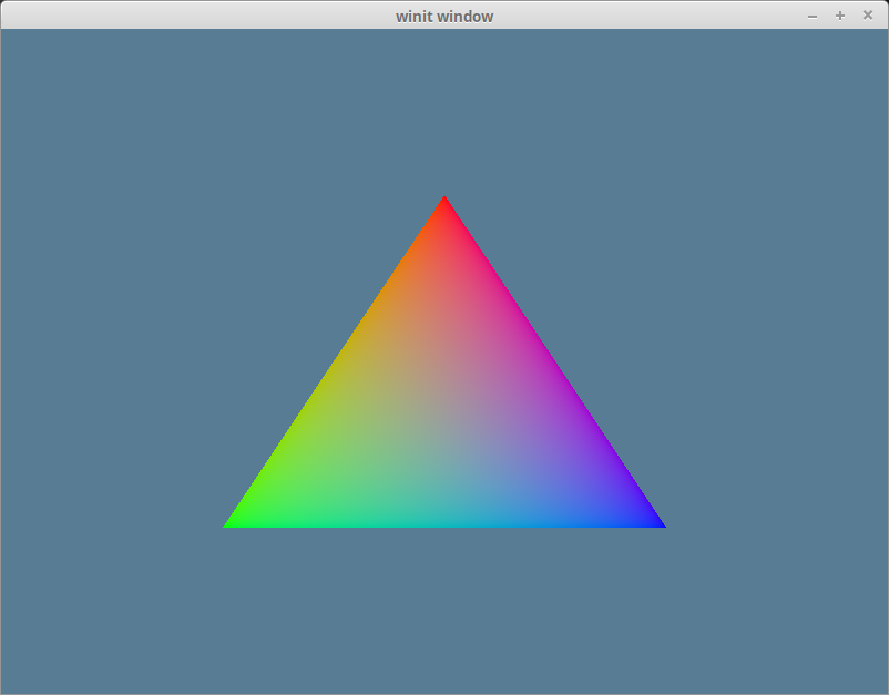
}如果做的正确无误,运行程序应该就能看到一个下边这样的三角形:
索引缓冲区
从技术的角度来看,目前的示例并不需要索引缓冲区,但它们仍然很有用。当开始使用有大量三角形的模型时,索引缓冲区就会发挥作用。考虑一下下边的五边形:
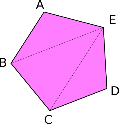
它总共有 5 个顶点和 3 个三角形。现在,如果我们想只用顶点来显示这样的东西,我们就需要以下顶点数据:
const VERTICES: &[Vertex] = &[
    Vertex { position: [-0.0868241, 0.49240386, 0.0], color: [0.5, 0.0, 0.5] }, // A
    Vertex { position: [-0.49513406, 0.06958647, 0.0], color: [0.5, 0.0, 0.5] }, // B
    Vertex { position: [0.44147372, 0.2347359, 0.0], color: [0.5, 0.0, 0.5] }, // E

    Vertex { position: [-0.49513406, 0.06958647, 0.0], color: [0.5, 0.0, 0.5] }, // B
    Vertex { position: [-0.21918549, -0.44939706, 0.0], color: [0.5, 0.0, 0.5] }, // C
    Vertex { position: [0.44147372, 0.2347359, 0.0], color: [0.5, 0.0, 0.5] }, // E

    Vertex { position: [-0.21918549, -0.44939706, 0.0], color: [0.5, 0.0, 0.5] }, // C
    Vertex { position: [0.35966998, -0.3473291, 0.0], color: [0.5, 0.0, 0.5] }, // D
    Vertex { position: [0.44147372, 0.2347359, 0.0], color: [0.5, 0.0, 0.5] }, // E
];你会注意到有些顶点被使用了不止一次。C 和 B 顶点被使用了两次,而 E 顶点被重复使用了 3 次。假设每个浮点数是 4 个字节,那么这意味着在我们用于 VERTICES 的 216 个字节中,有 96 个字节是重复的数据。如果能只把这些顶点列出来一次不是很好吗?我们可以做到这一点!
这,就是索引缓冲区发挥作用的地方。
大体上来说,我们在 VERTICES 中存储所有唯一的顶点,我们创建另一个缓冲区,将索引存储在 VERTICES 中的元素以创建三角形。下面还是以五边形为例:
// lib.rs
const VERTICES: &[Vertex] = &[
    Vertex { position: [-0.0868241, 0.49240386, 0.0], color: [0.5, 0.0, 0.5] }, // A
    Vertex { position: [-0.49513406, 0.06958647, 0.0], color: [0.5, 0.0, 0.5] }, // B
    Vertex { position: [-0.21918549, -0.44939706, 0.0], color: [0.5, 0.0, 0.5] }, // C
    Vertex { position: [0.35966998, -0.3473291, 0.0], color: [0.5, 0.0, 0.5] }, // D
    Vertex { position: [0.44147372, 0.2347359, 0.0], color: [0.5, 0.0, 0.5] }, // E
];

const INDICES: &[u16] = &[
    0, 1, 4,
    1, 2, 4,
    2, 3, 4,
];现在这种设置下,VERTICES 占用了 120 个字节,而 INDICES 只有 18 个字节,因为 u16 类型是 2 个字节长。在这种情况下,wgpu 会自动增加 2 个字节的填充,以确保缓冲区被对齐到 4 个字节,但它仍然只有 20 个字节。五边形总共是 140 字节,这意味着我们节省了 76 个字节! 这可能看起来不多,但当处理数十万的三角形时,索引可以节省大量的内存。
为了使用索引,有几处我们需要修改。首先需要创建一个缓冲区来存储索引。在 WgpuApp 的 new() 函数中,创建了 vertex_buffer 之后创建 index_buffer。同时将 num_vertices 改为num_indices,令其值等于 INDICES.len()。
let vertex_buffer = device.create_buffer_init(
    &wgpu::util::BufferInitDescriptor {
        label: Some("Vertex Buffer"),
        contents: bytemuck::cast_slice(VERTICES),
        usage: wgpu::BufferUsages::VERTEX,
    }
);
// 新添加!
let index_buffer = device.create_buffer_init(
    &wgpu::util::BufferInitDescriptor {
        label: Some("Index Buffer"),
        contents: bytemuck::cast_slice(INDICES),
        usage: wgpu::BufferUsages::INDEX,
    }
);
let num_indices = INDICES.len() as u32;我们不需要为索引实现 Pod 和 Zeroable,因为 bytemuck 已经为 u16 等基本类型实现了它们。只需将 index_buffer 和 num_indices 添加到 WgpuApp 结构体中。
struct WgpuApp {
    app: AppSurface,
    render_pipeline: wgpu::RenderPipeline,
    size: PhysicalSize<u32>,
    size_changed: bool,
    render_pipeline: wgpu::RenderPipeline,
    vertex_buffer: wgpu::Buffer,
    // 新添加!
    index_buffer: wgpu::Buffer,
    num_indices: u32,
}然后在构造函数中填充这些字段:
Self {
    app,
    size,
    size_changed: false,
    render_pipeline,
    vertex_buffer,
    // 新添加!
    index_buffer,
    num_indices,
}我们现在所要做的就是更新 render() 函数来使用 index_buffer:
// render()
render_pass.set_pipeline(&self.render_pipeline);
render_pass.set_vertex_buffer(0, self.vertex_buffer.slice(..));
render_pass.set_index_buffer(self.index_buffer.slice(..), wgpu::IndexFormat::Uint16); // 1.
render_pass.draw_indexed(0..self.num_indices, 0, 0..1); // 2.有几点需要注意:
- 命令名称是
set_index_buffer而不是set_index_buffers, 一次绘制(draw_XXX())只能设置一个索引缓冲区。但是,你可以在一个渲染通道内调用多次绘制,每次都设置不同的索引缓冲区。 - 当使用索引缓冲区时,需使用
draw_indexed来绘制,draw命令会忽略索引缓冲区。还需确保你使用的是索引数(num_indices)而非顶点数,否则你的模型要么画错,要么因为没有足够的索引数而导致程序恐慌(panic)。
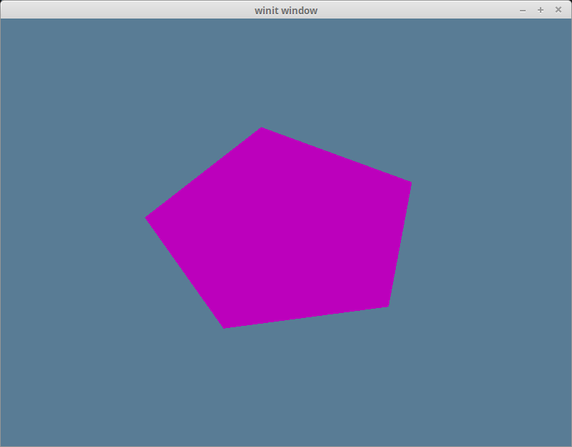
完成这些后,运行程序应该就能看到窗口里有一个洋红色的五边形了:
颜色校正
如果在洋红色五角星上使用取色器,你会得到一个 #BC00BC 的十六进制值。如果把它转换成 RGB 值会得到(188, 0, 188),将这些值除以 255 使其映射进 [0,1] 范围,大致会得到(0.737254902,0,0.737254902)。这与我们赋给顶点颜色的值不同,后者是(0.5, 0.0, 0.5)。其原因与色彩空间(Color Space)有关。
大多数显示器使用的色彩空间被称为 sRGB(事实上,目前市面上的中高端显示器已经支持 DisplayP3 甚至是 BT.2100 等广色域色彩空间,macOS 与 iOS 设备默认使用的就是 DisplayP3 色彩空间)。我们的展示平面(完全取决于从 surface.get_capabilities(&adapter).formats 返回的格式)默认支持 sRGB 纹理格式。sRGB 格式是根据颜色的相对亮度而不是实际亮度来存储的。其原因是人眼对光线的感知不是线性的。我们注意到较深的颜色比较浅的颜色有更多差异。
可以用下面的公式得到一个正确颜色的近似值。srgb_color = (rgb_color / 255) ^ 2.2。在 RGB 值为 (188, 0, 188) 的情况下,我们将得到 (0.511397819, 0.0, 0.511397819)。与我们的(0.5, 0.0, 0.5)有点偏差。虽然你可以通过调整公式来获得所需的数值,但使用纹理可能会节省很多时间,因为它们默认是以 sRGB 方式存储的,所以不会像顶点颜色那样出现颜色不准确的情况。我们会在下一课中介绍纹理。
假如你的显示设备使用的是 DisplayP3 或 BT.2100 等广色域色彩空间,那么当你使用取色器检查屏幕上的渲染结果时,拾取到的色值将与着色器内的返回值不一致。
这是因为目前 WebGPU 仅支持较小色域的 sRGB 色彩空间,而硬件会执行色彩空间转换(color space conversion)将 sRGB 色值映射到更广的色域来显示到屏幕上,因此,使用取色器拾取到的色值是经过转换后的值。
挑战
使用顶点缓冲区和索引缓冲区创建一个比教程里做的更复杂的形状(也就是三个以上的三角形),并用空格键在两者之间切换。