法线映射
添加光照后,我们的场景已经看起来很不错了。不过,对象表面还缺少实物的那种凹凸细节。如果使用的纹理是光滑的就不是问题,但是砖块纹理应该是比较粗糙的。 我们可以给模型添加更多的三角形来雕刻出表面的凹凸细节,但这将使得顶点数据倍增而渲染变慢,而且也很难知道在哪里添加新的三角形。这,就是法线映射(Normal Mapping)的用武之地了。
法线映射也叫凹凸映射(Bump Mapping),是一种纹理映射技术,它不用增加模型的几何复杂度就能够模拟具有复杂凹凸细节的表面。与简单的纹理映射不同,当绘制对象的表面时,法线映射技术通过扰动表面的法向量来改变它的形状,使得着色处理后的颜色能反映出表面几何特性的变化。
还记得在实例化绘制教程中,我们尝试了在纹理中存储实例数据吗?法线贴图(Normal Map)就是存储着法向量数据的纹理!除了顶点法向量外,我们还将在光照计算中使用法线贴图中的法向量。
我们的砖块纹理对应的法线贴图(也就是法线纹理)长这样:
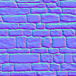
纹理的 r、g、b 分量对应于法向量的 x、y 和 z 坐标分量。所有的 z 值都应该是正的,这就是为什么法线贴图有一个蓝色的色调。
我们来修改 model.rs 中的材质 Material 结构体,新增一个法线纹理 normal_texture 字段:
pub struct Material {
    pub name: String,
    pub diffuse_texture: texture::Texture,
    pub normal_texture: texture::Texture, // 更新!
    pub bind_group: wgpu::BindGroup,
}还得更新纹理绑定组布局 texture_bind_group_layout 以包括法线贴图:
let texture_bind_group_layout = device.create_bind_group_layout(&wgpu::BindGroupLayoutDescriptor {
    entries: &[
        // ...
        // 法线贴图
        wgpu::BindGroupLayoutEntry {
            binding: 2,
            visibility: wgpu::ShaderStages::FRAGMENT,
            ty: wgpu::BindingType::Texture {
                multisampled: false,
                sample_type: wgpu::TextureSampleType::Float { filterable: true },
                view_dimension: wgpu::TextureViewDimension::D2,
            },
            count: None,
        },
        wgpu::BindGroupLayoutEntry {
            binding: 3,
            visibility: wgpu::ShaderStages::FRAGMENT,
            ty: wgpu::BindingType::Sampler(wgpu::SamplerBindingType::Filtering),
            count: None,
        },
    ],
    label: Some("texture_bind_group_layout"),
});在 resources.rs 的 load_model() 函数中创建材质的循环里,添加以下代码来实际加载法线贴图:
// resources.rs
let mut materials = Vec::new();
for m in obj_materials? {
    let diffuse_texture = load_texture(&m.diffuse_texture, device, queue).await?;
    // 新增!
    let normal_texture = load_texture(&m.normal_texture, device, queue).await?;

    materials.push(model::Material::new(
        device,
        &m.name,
        diffuse_texture,
        normal_texture, // 新增!
        layout,
    ));
}上面使用的 Material::new() 函数的具体代码如下:
impl Material {
    pub fn new(
        device: &wgpu::Device,
        name: &str,
        diffuse_texture: texture::Texture,
        normal_texture: texture::Texture, // 新增!
        layout: &wgpu::BindGroupLayout,
    ) -> Self {
        let bind_group = device.create_bind_group(&wgpu::BindGroupDescriptor {
            layout,
            entries: &[
                wgpu::BindGroupEntry {
                    binding: 0,
                    resource: wgpu::BindingResource::TextureView(&diffuse_texture.view),
                },
                wgpu::BindGroupEntry {
                    binding: 1,
                    resource: wgpu::BindingResource::Sampler(&diffuse_texture.sampler),
                },
                // 新增!
                wgpu::BindGroupEntry {
                    binding: 2,
                    resource: wgpu::BindingResource::TextureView(&normal_texture.view),
                },
                wgpu::BindGroupEntry {
                    binding: 3,
                    resource: wgpu::BindingResource::Sampler(&normal_texture.sampler),
                },
            ],
            label: Some(name),
        });

        Self {
            name: String::from(name),
            diffuse_texture,
            normal_texture, // 新增!
            bind_group,
        }
    }
}现在我们可以在片元着色器中使用纹理了:
// 片元着色器

@group(0) @binding(0)
var t_diffuse: texture_2d<f32>;
@group(0)@binding(1)
var s_diffuse: sampler;
@group(0)@binding(2)
var t_normal: texture_2d<f32>;
@group(0) @binding(3)
var s_normal: sampler;

@fragment
fn fs_main(in: VertexOutput) -> @location(0) vec4f {
    let object_color: vec4f = textureSample(t_diffuse, s_diffuse, in.tex_coords);
    let object_normal: vec4f = textureSample(t_normal, s_normal, in.tex_coords);
    // 环境光强度
    let ambient_strength = 0.1;
    let ambient_color = light.color * ambient_strength;

    // Create the lighting vectors
    let tangent_normal = object_normal.xyz * 2.0 - 1.0;
    let light_dir = normalize(light.position - in.world_position);
    let view_dir = normalize(camera.view_pos.xyz - in.world_position);
    let half_dir = normalize(view_dir + light_dir);

    let diffuse_strength = max(dot(tangent_normal, light_dir), 0.0);
    let diffuse_color = light.color * diffuse_strength;

    let specular_strength = pow(max(dot(tangent_normal, half_dir), 0.0), 32.0);
    let specular_color = specular_strength * light.color;

    let result = (ambient_color + diffuse_color + specular_color) * object_color.xyz;

    return vec4f(result, object_color.a);
}如果现在运行代码,你会发现渲染效果看起来不太对劲。让我们将效果与上一个教程比较一下:
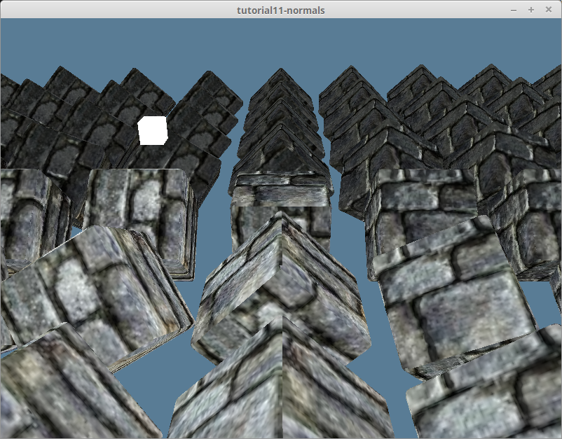
场景中应该被点亮的部分是黑暗的,反之亦然。
从切空间到世界空间
在光照教程的法线矩阵 部分有提到:我们是在世界空间中进行光照计算的。也就是说,整个场景的方向是相对于世界坐标系而言的。 从法线纹理中提取的法向量都处在正 Z 方向上,也就是说我们的光照计算认为模型的所有表面都朝向大致相同的方向。这被称为切空间(Tangent Space,也叫做切向量空间)。
光照教程 中我们用顶点法向量来表示表面的方向。现在,可以用它来将法线贴图中的法向量从切空间变换到世界空间。实现此变换需要用到一点点线性代数。
我们将创建一个矩阵,代表相对于顶点法向量的坐标空间(Coordinate Space)。然后使用它来变换法线贴图数据,使其处于世界空间:
let coordinate_system = mat3x3f(
    vec3(1, 0, 0), // x axis (右)
    vec3(0, 1, 0), // y axis (上)
    vec3(0, 0, 1)  // z axis (前)
);切向量与副切向量
我们已经有了需要的 3 个向量中的一个,即法向量。另外两个是切向量(Tangent Vector)与副切向量(Bitangent Vector, 也被叫作副法向量(Binormal))。切向量是与法向量垂直且表面平行的向量(也就是不与表面相交)。副切向量是同时垂直于由法向量与切向量的向量,所以可以由法向量与切向量的叉积计算得出。切向量、副切向量和法向量一起分别代表坐标空间 x、y 和 z 轴。
一些模型格式会在顶点数据中包括切向量和副切向量,但 OBJ 没有。我们得手动计算,可以从现有的顶点数据中推导出切向量与副切向量。请看下图:

可以使用三角形的边和法线来计算切向量与副切向量。首先,我们需要更新在 model.rs 中的顶点 ModelVertex 结构体:
#[repr(C)]
#[derive(Copy, Clone, Debug, bytemuck::Pod, bytemuck::Zeroable)]
pub struct ModelVertex {
    position: [f32; 3],
    tex_coords: [f32; 2],
    normal: [f32; 3],
    // 新增!
    tangent: [f32; 3],
    bitangent: [f32; 3],
}同时也需要更新顶点缓冲区布局 VertexBufferLayout:
impl Vertex for ModelVertex {
    fn desc<'a>() -> wgpu::VertexBufferLayout<'a> {
        use core::mem;
        wgpu::VertexBufferLayout {
            array_stride: mem::size_of::<ModelVertex>() as wgpu::BufferAddress,
            step_mode: wgpu::VertexStepMode::Vertex,
            attributes: &[
                // ...

                // Tangent and bitangent
                wgpu::VertexAttribute {
                    offset: mem::size_of::<[f32; 8]>() as wgpu::BufferAddress,
                    shader_location: 3,
                    format: wgpu::VertexFormat::Float32x3,
                },
                wgpu::VertexAttribute {
                    offset: mem::size_of::<[f32; 11]>() as wgpu::BufferAddress,
                    shader_location: 4,
                    format: wgpu::VertexFormat::Float32x3,
                },
            ],
        }
    }
}现在可以计算新的切向量与副切向量了, 用以下代码来更新 resource.rs 中 load_model() 函数的网格生成:
let meshes = models
    .into_iter()
    .map(|m| {
        let mut vertices = (0..m.mesh.positions.len() / 3)
            .map(|i| model::ModelVertex {
                position: [
                    m.mesh.positions[i * 3],
                    m.mesh.positions[i * 3 + 1],
                    m.mesh.positions[i * 3 + 2],
                ],
                tex_coords: [m.mesh.texcoords[i * 2], m.mesh.texcoords[i * 2 + 1]],
                normal: [
                    m.mesh.normals[i * 3],
                    m.mesh.normals[i * 3 + 1],
                    m.mesh.normals[i * 3 + 2],
                ],
                // 随后会计算实际值来替换
                tangent: [0.0; 3],
                bitangent: [0.0; 3],
            })
            .collect::<Vec<_>>();

        let indices = &m.mesh.indices;
        let mut triangles_included = vec![0; vertices.len()];

        // 遍历三角形的三个顶点来计算切向量与副切向量.
        for c in indices.chunks(3) {
            let v0 = vertices[c[0] as usize];
            let v1 = vertices[c[1] as usize];
            let v2 = vertices[c[2] as usize];

            let pos0: glam::Vec3 = v0.position.into();
            let pos1: glam::Vec3 = v1.position.into();
            let pos2: glam::Vec3 = v2.position.into();

            let uv0: glam::Vec2 = v0.tex_coords.into();
            let uv1: glam::Vec2 = v1.tex_coords.into();
            let uv2: glam::Vec2 = v2.tex_coords.into();

            // 计算三角形的边
            let delta_pos1 = pos1 - pos0;
            let delta_pos2 = pos2 - pos0;

            // 计算切向量/副切向量需要用到的两个方向向量
            let delta_uv1 = uv1 - uv0;
            let delta_uv2 = uv2 - uv0;

            // 求解以下方程组
            //     delta_pos1 = delta_uv1.x * T + delta_u.y * B
            //     delta_pos2 = delta_uv2.x * T + delta_uv2.y * B
            // 幸运的是,在我发现这个方程的地方提供了如下求解方案!
            let r = 1.0 / (delta_uv1.x * delta_uv2.y - delta_uv1.y * delta_uv2.x);
            let tangent = (delta_pos1 * delta_uv2.y - delta_pos2 * delta_uv1.y) * r;
            // 我们翻转副切向量以启用具有 wgpu 纹理坐标系的右手标架的法线贴图
            let bitangent = (delta_pos2 * delta_uv1.x - delta_pos1 * delta_uv2.x) * -r;

            // 我们为三角形中的每个顶点使用相同的切向量/副切向量
            vertices[c[0] as usize].tangent =
                (tangent + glam::Vec3::from_array(vertices[c[0] as usize].tangent)).into();
            vertices[c[1] as usize].tangent =
                (tangent + glam::Vec3::from_array(vertices[c[1] as usize].tangent)).into();
            vertices[c[2] as usize].tangent =
                (tangent + glam::Vec3::from_array(vertices[c[2] as usize].tangent)).into();
            vertices[c[0] as usize].bitangent =
                (bitangent + glam::Vec3::from_array(vertices[c[0] as usize].bitangent)).into();
            vertices[c[1] as usize].bitangent =
                (bitangent + glam::Vec3::from_array(vertices[c[1] as usize].bitangent)).into();
            vertices[c[2] as usize].bitangent =
                (bitangent + glam::Vec3::from_array(vertices[c[2] as usize].bitangent)).into();

            // 用于计算顶点上切向量/副切向量的平均值
            triangles_included[c[0] as usize] += 1;
            triangles_included[c[1] as usize] += 1;
            triangles_included[c[2] as usize] += 1;
        }

        // 计算切向量/副切向量的平均值
        for (i, n) in triangles_included.into_iter().enumerate() {
            let denom = 1.0 / n as f32;
            let mut v = &mut vertices[i];
            v.tangent = (glam::Vec3::from_array(v.tangent) * denom).into();
            v.bitangent = (glam::Vec3::from_array(v.bitangent) * denom).into();
        }

        let vertex_buffer = device.create_buffer_init(&wgpu::util::BufferInitDescriptor {
            label: Some(&format!("{:?} Vertex Buffer", file_name)),
            contents: bytemuck::cast_slice(&vertices),
            usage: wgpu::BufferUsages::VERTEX,
        });
        let index_buffer = device.create_buffer_init(&wgpu::util::BufferInitDescriptor {
            label: Some(&format!("{:?} Index Buffer", file_name)),
            contents: bytemuck::cast_slice(&m.mesh.indices),
            usage: wgpu::BufferUsages::INDEX,
        });

        model::Mesh {
            name: file_name.to_string(),
            vertex_buffer,
            index_buffer,
            num_elements: m.mesh.indices.len() as u32,
            material: m.mesh.material_id.unwrap_or(0),
        }
    })
.collect::<Vec<_>>();从世界空间到切空间
由于法线贴图默认是在切空间中,该计算中使用的所有其他变量也得变换为切空间。我们需要在顶点着色器中构建切向量矩阵,首先,修改 VertexInput 来包括之前计算的切向量与副切向量:
struct VertexInput {
    @location(0) position: vec3f,
    @location(1) tex_coords: vec2f;
    @location(2) normal: vec3f;
    @location(3) tangent: vec3f;
    @location(4) bitangent: vec3f;
};接下来构建切向量矩阵 tangent_matrix,然后将顶点,光源和视图坐标变换到切空间:
struct VertexOutput {
    @builtin(position) clip_position: vec4f;
    @location(0) tex_coords: vec2f;
    // 更新!
    @location(1) tangent_position: vec3f;
    @location(2) tangent_light_position: vec3f;
    @location(3) tangent_view_position: vec3f;
};

@vertex
fn vs_main(
    model: VertexInput,
    instance: InstanceInput,
) -> VertexOutput {
    // ...
    let normal_matrix = mat3x3f(
        instance.normal_matrix_0,
        instance.normal_matrix_1,
        instance.normal_matrix_2,
    );

    // 构建切向量矩阵
    let world_normal = normalize(normal_matrix * model.normal);
    let world_tangent = normalize(normal_matrix * model.tangent);
    let world_bitangent = normalize(normal_matrix * model.bitangent);
    let tangent_matrix = transpose(mat3x3f(
        world_tangent,
        world_bitangent,
        world_normal,
    ));

    let world_position = model_matrix * vec4f(model.position, 1.0);

    var out: VertexOutput;
    out.clip_position = camera.view_proj * world_position;
    out.tex_coords = model.tex_coords;
    out.tangent_position = tangent_matrix * world_position.xyz;
    out.tangent_view_position = tangent_matrix * camera.view_pos.xyz;
    out.tangent_light_position = tangent_matrix * light.position;
    return out;
}最后,更新片元着色器以使用这些转换后的光照值:
@fragment
fn fs_main(in: VertexOutput) -> @location(0) vec4f {
    // Sample textures..

    // 光照计算需要的向量
    let tangent_normal = object_normal.xyz * 2.0 - 1.0;
    let light_dir = normalize(in.tangent_light_position - in.tangent_position);
    let view_dir = normalize(in.tangent_view_position - in.tangent_position);

    // 执行光照计算...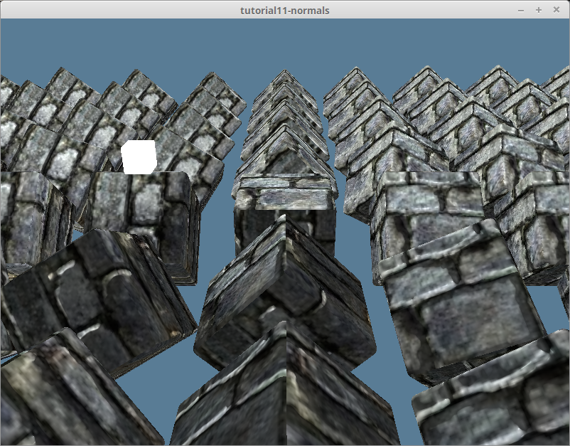
}完成上边的计算,我们会得到如下渲染效果:
sRGB 与法线纹理
光线的强度是对其能量的物理度量,而亮度 (brightness) 度量的是人眼所感知到的光线强度。 由于人眼中的光感受器对不同波长的光线能量的响应不同,即使红光和绿光的物理强度相同,在我们看来它们也并不具有相同的亮度,事实上,人眼是按对数关系来感知光线强度的。根据人类视觉系统所具有的这种特性,如果希望亮度看起来按等间隔的步长递增,那么赋给像素的光强值应该按指数的形式递增。显示设备可以根据所能产生的最小和最大光强值通过计算得到亮度变化的步长。
sRGB 色彩空间是一种于计算机显示设备和打印机等设备的标准颜色系统,包括 WebGPU 在内的大部分图形绘制系统都支持 sRGB。它通过对色值的 𝛄 (gamma) 编码,实现了图像在有限的色值范围(红、绿、蓝每个颜色通道的取值都在 [0, 255] 范围内)内隐藏人眼对色彩的感知差异。
GPU 硬件对 sRGB 色彩空间提供了特殊支持,可以将颜色值从线性值转换到 𝛄 编码,并通过 𝛄 校正(Gamma Correction)解码回线性值。 我们一直在使用 Rgba8UnormSrgb 格式来制作所有的纹理。Srgb 位就是指示 wgpu:
- 当着色器代码对 sRGB 格式的纹理进行采样时,GPU 硬件要将其从 sRGB 采样值解码为线性值再返回给着色器;
- 当着色器代码写入线性颜色值到 sRGB 格式的纹理时,GPU 硬件要对其进行 𝛄 编码后再写入;
如果纹理数据不是基于 sRGB 色彩空间制作的,但指定了 RgbaUnormSrgb 格式,会由于改变了 GPU 对纹理的采样方式而导致渲染结果与预期不符。 这可以通过在创建纹理时使用 Rgba8Unorm 来避免。让我们给 Texture 结构体添加一个 is_normal_map 参数。
pub fn from_image(
    device: &wgpu::Device,
    queue: &wgpu::Queue,
    img: &image::DynamicImage,
    label: Option<&str>,
    is_normal_map: bool, // 新增!
) -> Result<(Self, wgpu::CommandBuffer), failure::Error> {
    // ...
    let texture = device.create_texture(&wgpu::TextureDescriptor {
        label,
        size,
        mip_level_count: 1,
        sample_count: 1,
        dimension: wgpu::TextureDimension::D2,
        // 更新!
        format: if is_normal_map {
            wgpu::TextureFormat::Rgba8Unorm
        } else {
            wgpu::TextureFormat::Rgba8UnormSrgb
        },
        usage: wgpu::TextureUsages::TEXTURE_BINDING | wgpu::TextureUsages::COPY_DST,
        view_formats: &[],
    });

    // ...

    Ok((Self { texture, view, sampler }, cmd_buffer))
}并将这一修改同步到其他有关的函数:
pub fn from_bytes(
    device: &wgpu::Device,
    queue: &wgpu::Queue,
    bytes: &[u8],
    label: &str,
    is_normal_map: bool, // 新增!
) -> Result<Self> {
    let img = image::load_from_memory(bytes)?;
    Self::from_image(device, queue, &img, Some(label), is_normal_map) // 更新!
}同时也还要更新 resource.rs:
pub async fn load_texture(
    file_name: &str,
    is_normal_map: bool,
    device: &wgpu::Device,
    queue: &wgpu::Queue,
) -> anyhow::Result<texture::Texture> {
    let data = load_binary(file_name).await?;
    texture::Texture::from_bytes(device, queue, &data, file_name, is_normal_map)
}

pub async fn load_model(
    file_name: &str,
    device: &wgpu::Device,
    queue: &wgpu::Queue,
    layout: &wgpu::BindGroupLayout,
) -> anyhow::Result<model::Model> {
    // ...

    let mut materials = Vec::new();
    for m in obj_materials? {
        let diffuse_texture = load_texture(&m.diffuse_texture, false, device, queue).await?; // 更新!
        let normal_texture = load_texture(&m.normal_texture, true, device, queue).await?; // 更新!

        materials.push(model::Material::new(
            device,
            &m.name,
            diffuse_texture,
            normal_texture,
            layout,
        ));
    }
}现在的渲染效果如下:

试试其他材质
现在改用其他材质来试试效果,在 DrawModel trait 中添加了一个 draw_model_instanced_with_material() 接口并在渲染通道对象上实现此接口:
pub trait DrawModel<'a> {
    // ...
    fn draw_model_instanced_with_material(
        &mut self,
        model: &'a Model,
        material: &'a Material,
        instances: Range<u32>,
        camera_bind_group: &'a wgpu::BindGroup,
        light_bind_group: &'a wgpu::BindGroup,
    );
}

impl<'a, 'b> DrawModel<'b> for wgpu::RenderPass<'a>
where
    'b: 'a,
{
    // ...
    fn draw_model_instanced_with_material(
        &mut self,
        model: &'b Model,
        material: &'b Material,
        instances: Range<u32>,
        camera_bind_group: &'b wgpu::BindGroup,
        light_bind_group: &'b wgpu::BindGroup,
    ) {
        for mesh in &model.meshes {
            self.draw_mesh_instanced(mesh, material, instances.clone(), camera_bind_group, light_bind_group);
        }
    }
}我找到了一个鹅卵石纹理及匹配的法线贴图,并为它创建一个叫 debug_material 的材质实例:
// lib.rs
impl WgpuAppAction for WgpuApp {
    async fn new(window: Arc<winit::window::Window>) -> Self {
        // ...
        let debug_material = {
            let diffuse_bytes = include_bytes!("../res/cobble-diffuse.png");
            let normal_bytes = include_bytes!("../res/cobble-normal.png");

            let diffuse_texture = texture::Texture::from_bytes(&device, &queue, diffuse_bytes, "res/alt-diffuse.png", false).unwrap();
            let normal_texture = texture::Texture::from_bytes(&device, &queue, normal_bytes, "res/alt-normal.png", true).unwrap();

            model::Material::new(&device, "alt-material", diffuse_texture, normal_texture, &texture_bind_group_layout)
        };
        Self {
            // ...
            #[allow(dead_code)]
            debug_material,
        }
    }
}然后调用刚实现的 draw_model_instanced_with_material() 函数来使用 debug_material 渲染:
render_pass.set_pipeline(&self.render_pipeline);
render_pass.draw_model_instanced_with_material(
    &self.obj_model,
    &self.debug_material,
    0..self.instances.len() as u32,
    &self.camera_bind_group,
    &self.light_bind_group,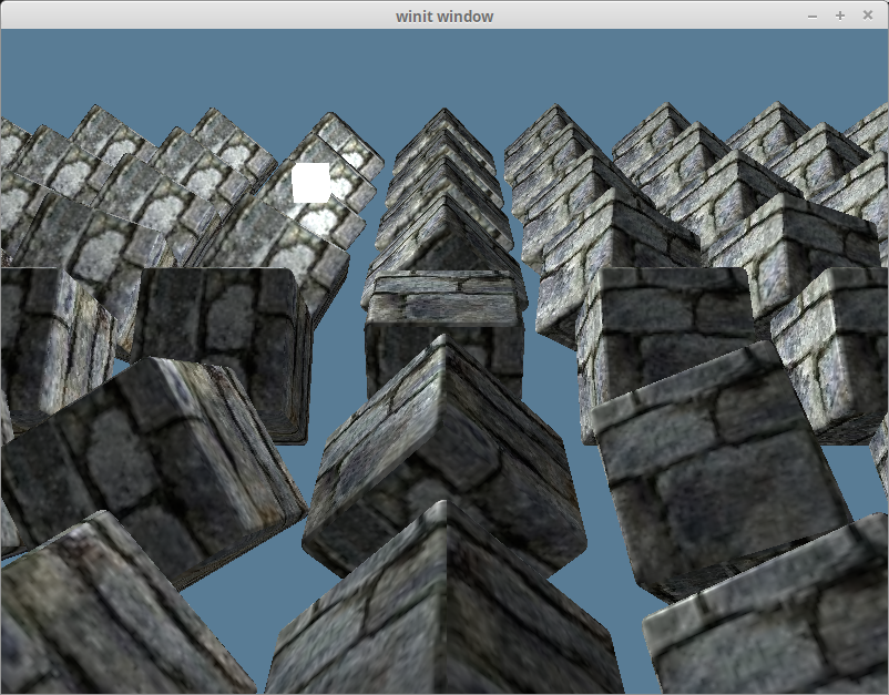
);得到的渲染效果如下:
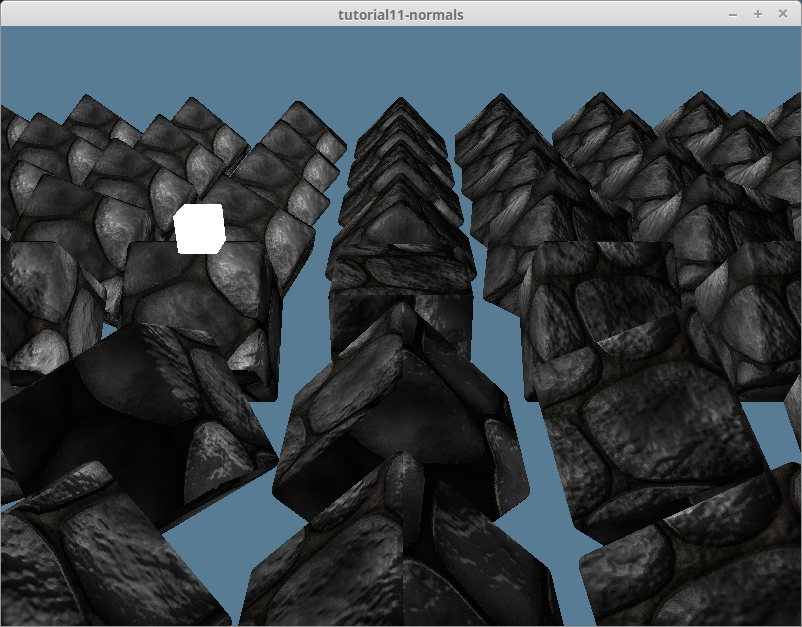
上面使用的纹理可以在 Github 源码库中找到。