纹理和绑定组
目前为止,我们一直在绘制简单的图形。当然可以只用三角形来做游戏,而试图绘制高精度的对象又会极大地限制能运行我们游戏的设备。不过,可以用 纹理 来解决此问题。
纹理(Textures)是叠加在三角形网格(Mesh)上的图像,使其看起来有丰富的细节。有多种类型的纹理,如法线贴图(Normal Maps,也就是法线纹理)、凹凸贴图(Bump Maps)、镜面贴图和漫反射贴图。下边将讨论漫反射贴图,简单来说也就是颜色纹理。
加载图像文件
要把一个图像映射到对象网格上,首先是需要有一个图像文件。就使用下边这棵快乐的小树吧:

我们将使用 image 包 来加载这棵树。先把它添加到依赖项中:
[dependencies.image]
version = "0.24"
default-features = false
features = ["png", "jpeg"]image 包含的 jpeg 解码器使用 rayon 来加速线程的解码速度。WASM 目前不支持线程,所以我们需要禁用这一特性,这样代码在尝试加载网络上的 jpeg 时就不会崩溃。
在 WASM 中解码 jpeg 性能不高。如果你想在 WASM 中加快图像加载速度,可以选择使用浏览器的内置解码器来替换 wasm-bindgen 构建时使用 的 image。这涉及到在 Rust 中创建一个 <img> 标记来获取图像,然后创建一个 <canvas> 来获取像素数据,我把这留作读者的练习。
在 WgpuApp 的 new() 函数中,于 AppSurface::new(window).await 之后添加以下代码:
let app = AppSurface::new(window).await;

// 新添加!
let diffuse_bytes = include_bytes!("happy-tree.png");
let diffuse_image = image::load_from_memory(diffuse_bytes).unwrap();
let diffuse_rgba = diffuse_image.to_rgba8();

use image::GenericImageView;
let dimensions = diffuse_image.dimensions();此处代码从图像文件中读取字节,并将其加载到 image 对象中,然后转换为 rgba 动态数组。我们还保存了图像的尺寸信息以便在创建实际纹理时使用。
现在我们来创建纹理:
let texture_size = wgpu::Extent3d {
    width: dimensions.0,
    height: dimensions.1,
    depth_or_array_layers: 1,
};
let diffuse_texture = device.create_texture(
    &wgpu::TextureDescriptor {
        // 所有纹理都是以 3D 形式存储的,我们通过设置深度 1 来表示 2D 纹理
        size: texture_size,
        mip_level_count: 1, // 后面会详细介绍此字段
        sample_count: 1,
        dimension: wgpu::TextureDimension::D2,
        // 大多数图像都是使用 sRGB 来存储的,我们需要在这里指定。
        format: wgpu::TextureFormat::Rgba8UnormSrgb,
        // TEXTURE_BINDING 表示我们要在着色器中使用这个纹理。
        // COPY_DST 表示我们能将数据复制到这个纹理上。
        usage: wgpu::TextureUsages::TEXTURE_BINDING | wgpu::TextureUsages::COPY_DST,
        label: Some("diffuse_texture"),
        view_formats: &[],
    }
);填充数据到纹理中
Texture 结构体没有函数可以直接与数据交互。但我们可以使用之前创建的命令队列上的 write_texture 命令来填充纹理数据。下边是具体代码:
queue.write_texture(
    // 告诉 wgpu 将像素数据复制到何处
    wgpu::TexelCopyTextureInfo {
        texture: &diffuse_texture,
        mip_level: 0,
        origin: wgpu::Origin3d::ZERO,
        aspect: wgpu::TextureAspect::All,
    },
    // 实际像素数据
    &diffuse_rgba,
    // 纹理的内存布局
    wgpu::TexelCopyBufferLayout {
        offset: 0,
        bytes_per_row: Some(4 * dimensions.0),
        rows_per_image: Some(dimensions.1),
    },
    texture_size,
);填充纹理数据的经典方式是将像素数据先复制到一个缓冲区,然后再从缓冲区复制到纹理中。使用 write_texture 更有效率,因为它少用了一个缓冲区 -- 不过这里还是介绍一下,以防读者有需要:
let buffer = device.create_buffer_init(
    &wgpu::util::BufferInitDescriptor {
        label: Some("Temp Buffer"),
        contents: &diffuse_rgba,
        usage: wgpu::BufferUsages::COPY_SRC,
    }
);

let mut encoder = device.create_command_encoder(&wgpu::CommandEncoderDescriptor {
    label: Some("texture_buffer_copy_encoder"),
});

encoder.copy_buffer_to_texture(
    wgpu::TexelCopyBufferInfo {
        buffer: &buffer,
        offset: 0,
        bytes_per_row: 4 * dimensions.0,
        rows_per_image: dimensions.1,
    },
    wgpu::TexelCopyTextureInfo {
        texture: &diffuse_texture,
        mip_level: 0,
        array_layer: 0,
        origin: wgpu::Origin3d::ZERO,
    },
    size,
);

queue.submit(Some(encoder.finish()));值得注意的是 bytes_per_row 字段,这个值需要是 256 的倍数。查看 gif 教程 以了解更多细节。
纹理视图与采样器
现在纹理中已经有了数据,我们需要一种方法来使用它。这,就是纹理视图(TextureView)和采样器(Sampler)的用处。
纹理视图描述纹理及其关联的元数据。采样器控制纹理如何被 采样。采样工作类似于 GIMP/Photoshop 中的滴管工具。我们的程序在纹理上提供一个坐标(被称为 纹理坐标 ),然后采样器根据纹理和一些内部参数返回相应的颜色。
现在我们来定义 diffuse_texture_view 和 diffuse_sampler:
// 我们不需要过多地配置纹理视图,所以使用 wgpu 的默认值。
let diffuse_texture_view = diffuse_texture.create_view(&wgpu::TextureViewDescriptor::default());
let diffuse_sampler = device.create_sampler(&wgpu::SamplerDescriptor {
    address_mode_u: wgpu::AddressMode::ClampToEdge,
    address_mode_v: wgpu::AddressMode::ClampToEdge,
    address_mode_w: wgpu::AddressMode::ClampToEdge,
    mag_filter: wgpu::FilterMode::Linear,
    min_filter: wgpu::FilterMode::Nearest,
    mipmap_filter: wgpu::MipmapFilterMode::Nearest,
    ..Default::default()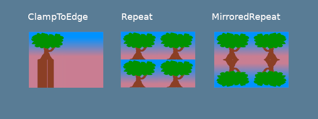
});address_mode_* 参数指定了如果采样器得到的纹理坐标超出了纹理边界时该如何处理。我们有几个选项可供选择:
ClampToEdge:任何在纹理外的纹理坐标将返回离纹理边缘最近的像素的颜色。Repeat。当纹理坐标超过纹理的尺寸时,纹理将重复。MirrorRepeat。类似于Repeat,但图像在越过边界时将翻转。
mag_filter 与 min_filter 字段描述了当采样足迹小于或大于一个纹素(Texel)时该如何处理。当场景中的贴图远离或靠近 camera 时,这两个字段的设置通常会有效果。
有 2 个选项:
Linear:在每个维度中选择两个纹素,并在它们的值之间返回线性插值。Nearest:返回离纹理坐标最近的纹素的值。这创造了一个从远处看比较清晰但近处有像素的图像。然而,如果你的纹理被设计成像素化的,比如像素艺术游戏,或者像 Minecraft 这样的体素游戏,这可能是符合预期的。
Mipmaps 是一个复杂的话题,需要在未来单独写一个章节。现在,我们可以说 mipmap_filter 的功能有点类似于 (mag/min)_filter,因为它告诉采样器如何在 mipmaps 之间混合。
其他字段使用了默认值。如果想了解字段详情,请查看 wgpu 文档。
现在,我们需要用到 BindGroup 和 PipelineLayout 来将所有这些不同的资源都接入。
绑定组
绑定组(BindGroup)描述了一组资源以及如何通过着色器访问它们。我们先来创建一个绑定组布局(BindGroupLayout):
let texture_bind_group_layout =
    device.create_bind_group_layout(&wgpu::BindGroupLayoutDescriptor {
        entries: &[
            wgpu::BindGroupLayoutEntry {
                binding: 0,
                visibility: wgpu::ShaderStages::FRAGMENT,
                ty: wgpu::BindingType::Texture {
                    multisampled: false,
                    view_dimension: wgpu::TextureViewDimension::D2,
                    sample_type: wgpu::TextureSampleType::Float { filterable: true },
                },
                count: None,
            },
            wgpu::BindGroupLayoutEntry {
                binding: 1,
                visibility: wgpu::ShaderStages::FRAGMENT,
                // This should match the filterable field of the
                // corresponding Texture entry above.
                ty: wgpu::BindingType::Sampler(wgpu::SamplerBindingType::Filtering),
                count: None,
            },
        ],
        label: Some("texture_bind_group_layout"),
});texture_bind_group_layout 有两个条目:一个是绑定到 0 资源槽的纹理,另一个是绑定到 1 资源槽的采样器。这两个绑定只对由 visibility 字段指定的片元着色器可见。这个字段的可选值是 NONE、VERTEX、FRAGMENT 或 COMPUTE 的任意按位或(|)组合。
现在使用绑定组布局(texture_bind_group_layout)来创建绑定组:
let diffuse_bind_group = device.create_bind_group(
    &wgpu::BindGroupDescriptor {
        layout: &texture_bind_group_layout,
        entries: &[
            wgpu::BindGroupEntry {
                binding: 0,
                resource: wgpu::BindingResource::TextureView(&diffuse_texture_view),
            },
            wgpu::BindGroupEntry {
                binding: 1,
                resource: wgpu::BindingResource::Sampler(&diffuse_sampler),
            }
        ],
        label: Some("diffuse_bind_group"),
    }
);看着这个,你可能会有一点似曾相识的感觉! 这是因为绑定组是绑定组布局的一个更具体的声明。它们分开的原因是,只要是共享同一个绑定组布局的绑定组,就能在运行时实时切换。创建的每个纹理和采样器都需要添加到一个绑定组中。为了达成目的,我们将为每个纹理创建一个新的绑定组。
让我们把 diffuse_bind_group 添加到 WgpuApp 结构体中:
struct WgpuApp {
    app: AppSurface,
    size: PhysicalSize<u32>,
    size_changed: bool,
    render_pipeline: wgpu::RenderPipeline,
    vertex_buffer: wgpu::Buffer,
    index_buffer: wgpu::Buffer,
    num_indices: u32,
    diffuse_bind_group: wgpu::BindGroup, // 新添加!
}确保我们在 new() 函数中返回这个字段:
impl WgpuAppAction for WgpuApp {
    async fn new(window: Arc<winit::window::Window>) -> Self {
        // ...
        Self {
            // ...
            // 新添加!
            diffuse_bind_group,
        }
    }
}现在,我们来在 render() 函数中使用绑定组:
// render()
// ...
render_pass.set_pipeline(&self.render_pipeline);
render_pass.set_bind_group(0, &self.diffuse_bind_group, &[]); // NEW!
render_pass.set_vertex_buffer(0, self.vertex_buffer.slice(..));
render_pass.set_index_buffer(self.index_buffer.slice(..), wgpu::IndexFormat::Uint16);

render_pass.draw_indexed(0..self.num_indices, 0, 0..1);管线布局
还记得在管线章节创建的管线布局(PipelineLayout)吗?现在我们终于可以使用它了! 管线布局包含一个管线可以使用的绑定组布局的列表。修改 render_pipeline_layout 以使用 texture_bind_group_layout:
async fn new(...) {
    // ...
    let render_pipeline_layout = device.create_pipeline_layout(
        &wgpu::PipelineLayoutDescriptor {
            label: Some("Render Pipeline Layout"),
            bind_group_layouts: &[Some(&texture_bind_group_layout)], // 新添加!
            immediate_size: 0,
        }
    );
    // ...
}修改 VERTICES 常量
对于 Vertex 的定义有几处需要修改。到目前为止,我们一直在使用 color 字段来设置网格颜色。现在我们要用 tex_coords 代替 color,这些坐标会被传递给采样器以获取纹素(Texel)的颜色。
由于 tex_coords 是二维的,需要修改这个字段的类型为两个浮点数的数组。
先来修改 Vertex 结构体:
#[repr(C)]
#[derive(Copy, Clone, Debug, bytemuck::Pod, bytemuck::Zeroable)]
struct Vertex {
    position: [f32; 3],
    tex_coords: [f32; 2], // 新添加!
}然后在 VertexBufferLayout 中反映这些变化:
impl Vertex {
    fn desc<'a>() -> wgpu::VertexBufferLayout<'a> {
        use core::mem;
        wgpu::VertexBufferLayout {
            array_stride: mem::size_of::<Vertex>() as wgpu::BufferAddress,
            step_mode: wgpu::VertexStepMode::Vertex,
            attributes: &[
                wgpu::VertexAttribute {
                    offset: 0,
                    shader_location: 0,
                    format: wgpu::VertexFormat::Float32x3,
                },
                wgpu::VertexAttribute {
                    offset: mem::size_of::<[f32; 3]>() as wgpu::BufferAddress,
                    shader_location: 1,
                    format: wgpu::VertexFormat::Float32x2, // NEW!
                },
            ]
        }
    }
}最后,需要修改 VERTICES,用以下代码替换现有的定义:
// Changed
const VERTICES: &[Vertex] = &[
    Vertex { position: [-0.0868241, 0.49240386, 0.0], tex_coords: [0.4131759, 0.99240386], }, // A
    Vertex { position: [-0.49513406, 0.06958647, 0.0], tex_coords: [0.0048659444, 0.56958647], }, // B
    Vertex { position: [-0.21918549, -0.44939706, 0.0], tex_coords: [0.28081453, 0.05060294], }, // C
    Vertex { position: [0.35966998, -0.3473291, 0.0], tex_coords: [0.85967, 0.1526709], }, // D
    Vertex { position: [0.44147372, 0.2347359, 0.0], tex_coords: [0.9414737, 0.7347359], }, // E
];修改着色器
有了新的 Vertex 结构体,现在是时候更新着色器了。首先需要将 tex_coords 传递给顶点着色器,然后将它们用于片元着色器,以便从采样器获得最终的颜色。让我们从顶点着色器开始:
// 顶点着色器

struct VertexInput {
    @location(0) position: vec3f,
    @location(1) tex_coords: vec2f,
}

struct VertexOutput {
    @builtin(position) clip_position: vec4f,
    @location(0) tex_coords: vec2f,
}

@vertex
fn vs_main(
    model: VertexInput,
) -> VertexOutput {
    var out: VertexOutput;
    out.tex_coords = model.tex_coords;
    out.clip_position = vec4f(model.position, 1.0);
    return out;
}现在顶点着色器输出了 tex_coords,我们需要改变片元着色器来接收它们。有了这些坐标,就可以使用采样器从纹理中获取纹素的颜色了:
// 片元着色器

@group(0) @binding(0)
var t_diffuse: texture_2d<f32>;
@group(0)@binding(1)
var s_diffuse: sampler;

@fragment
fn fs_main(in: VertexOutput) -> @location(0) vec4f {
    return textureSample(t_diffuse, s_diffuse, in.tex_coords);
}变量 t_diffuse 和 s_diffuse 就是所谓的 uniforms。我们将在 相机部分 中进一步讨论 uniforms。现在,我们需要知道的是,@group(x) 对应于 set_bind_group() 中的第一个参数,@binding(x) 与我们创建绑定组布局和绑定组时指定的 binding 值对应。
渲染结果
现在运行我们的程序,将得到如下渲染效果:
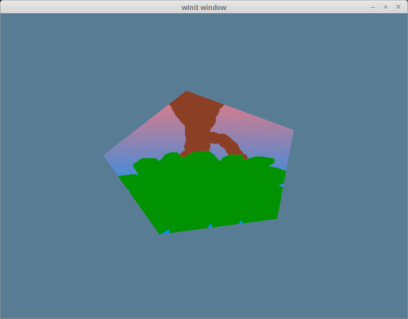
很奇怪,我们的树是颠倒的! 这是因为 wgpu 的世界坐标的 Y 轴朝上,而纹理坐标的 Y 轴朝下。换句话说,纹理坐标中的(0,0)对应于图像的左上方,而(1,1)是右下方:
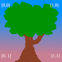
我们可以通过将每个纹理坐标的 y 坐标替换为 1 - y 来得到纹理的正确朝向:
const VERTICES: &[Vertex] = &[
    // 修改后的
    Vertex { position: [-0.0868241, 0.49240386, 0.0], tex_coords: [0.4131759, 0.00759614], }, // A
    Vertex { position: [-0.49513406, 0.06958647, 0.0], tex_coords: [0.0048659444, 0.43041354], }, // B
    Vertex { position: [-0.21918549, -0.44939706, 0.0], tex_coords: [0.28081453, 0.949397], }, // C
    Vertex { position: [0.35966998, -0.3473291, 0.0], tex_coords: [0.85967, 0.84732914], }, // D
    Vertex { position: [0.44147372, 0.2347359, 0.0], tex_coords: [0.9414737, 0.2652641], }, // E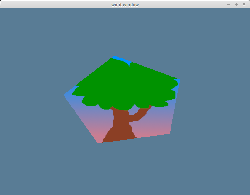
];现在我们就把树正确地放在五边形上了:
代码整理
为方便起见,让我们把纹理代码放到自己的模块中。我们首先将 anyhow 包添加到 Cargo.toml 文件中,以简化错误处理:
[dependencies]
image = "0.25"
glam = "0.32"
winit = "0.30"
env_logger = "0.11"
log = "0.4"
wgpu = "30"
bytemuck = { version = "1.22", features = [ "extern_crate_alloc", "min_const_generics" ] }
anyhow = "1.0" # NEW!然后,在一个名为 src/texture.rs 的新文件中,添加以下代码:
use image::GenericImageView;
use anyhow::*;

pub struct Texture {
    pub texture: wgpu::Texture,
    pub view: wgpu::TextureView,
    pub sampler: wgpu::Sampler,
}

impl Texture {
    pub fn from_bytes(
        device: &wgpu::Device,
        queue: &wgpu::Queue,
        bytes: &[u8],
        label: &str
    ) -> Result<Self> {
        let img = image::load_from_memory(bytes)?;
        Self::from_image(device, queue, &img, Some(label))
    }

    pub fn from_image(
        device: &wgpu::Device,
        queue: &wgpu::Queue,
        img: &image::DynamicImage,
        label: Option<&str>
    ) -> Result<Self> {
        let rgba = img.to_rgba8();
        let dimensions = img.dimensions();

        let size = wgpu::Extent3d {
            width: dimensions.0,
            height: dimensions.1,
            depth_or_array_layers: 1,
        };
        let texture = device.create_texture(
            &wgpu::TextureDescriptor {
                label,
                size,
                mip_level_count: 1,
                sample_count: 1,
                dimension: wgpu::TextureDimension::D2,
                format: wgpu::TextureFormat::Rgba8UnormSrgb,
                usage: wgpu::TextureUsages::TEXTURE_BINDING | wgpu::TextureUsages::COPY_DST,
                view_formats: &[],
            }
        );

        queue.write_texture(
            wgpu::TexelCopyTextureInfo {
                aspect: wgpu::TextureAspect::All,
                texture: &texture,
                mip_level: 0,
                origin: wgpu::Origin3d::ZERO,
            },
            &rgba,
            wgpu::TexelCopyBufferLayout {
                offset: 0,
                bytes_per_row: Some(4 * dimensions.0),
                rows_per_image: Some(dimensions.1),
            },
            size,
        );

        let view = texture.create_view(&wgpu::TextureViewDescriptor::default());
        let sampler = device.create_sampler(
            &wgpu::SamplerDescriptor {
                address_mode_u: wgpu::AddressMode::ClampToEdge,
                address_mode_v: wgpu::AddressMode::ClampToEdge,
                address_mode_w: wgpu::AddressMode::ClampToEdge,
                mag_filter: wgpu::FilterMode::Linear,
                min_filter: wgpu::FilterMode::Nearest,
                mipmap_filter: wgpu::MipmapFilterMode::Nearest,
                ..Default::default()
            }
        );

        Ok(Self { texture, view, sampler })
    }
}注意,我们使用的是 to_rgba8() 而不是 as_rgba8()。PNG 使用 as_rgba8() 没问题,因为它们有一个 alpha 通道。但是 JPEG 没有 alpha 通道,如果我们试图在 JPEG 纹理图像上调用 as_rgba8(),代码就会陷入恐慌。相反,我们可以使用 to_rgba8() 来处理没有 alpha 通道的图像,它会生成一个新的图像缓冲区。
在 lib.rs 文件的顶部添加以下代码来将 texture.rs 作为一个模块导入:
mod texture;new() 函数中的纹理创建代码现在变得简化多了:
surface.configure(&device, &config);
let diffuse_bytes = include_bytes!("happy-tree.png"); // CHANGED!
let diffuse_texture = texture::Texture::from_bytes(&device, &queue, diffuse_bytes, "happy-tree.png").unwrap(); // CHANGED!

// 到 `let texture_bind_group_layout = ...` 行为止的所有代码现在都可以移除了。我们仍然需要单独存储绑定组,因为纹理无须知道绑定组的布局。修改创建 diffuse_bind_group 的过程以使用diffuse_texture 的 view 和 sampler 字段:
let diffuse_bind_group = device.create_bind_group(
    &wgpu::BindGroupDescriptor {
        layout: &texture_bind_group_layout,
        entries: &[
            wgpu::BindGroupEntry {
                binding: 0,
                resource: wgpu::BindingResource::TextureView(&diffuse_texture.view), // CHANGED!
            },
            wgpu::BindGroupEntry {
                binding: 1,
                resource: wgpu::BindingResource::Sampler(&diffuse_texture.sampler), // CHANGED!
            }
        ],
        label: Some("diffuse_bind_group"),
    }
);最后,需要更新 WgpuApp 中的字段以使用全新 Texture 结构体,在未来的教程中还会用到它:
struct WgpuApp {
    // ...
    diffuse_bind_group: wgpu::BindGroup,
    diffuse_texture: texture::Texture, // NEW
}impl WgpuAppAction for WgpuApp {
async fn new(window: Arc<winit::window::Window>) -> Self {
// ...
Self {
// ...
num_indices,
diffuse_bind_group,
diffuse_texture, // NEW
}
}
}经过上边的整理,代码的工作方式还和以前一样,但我们现在有了一个更便利的方式来创建纹理。
挑战
另创建一个纹理,并在你按下空格键时交替使用。